MULTI-BANT RECEIVER
55 MHZ-801 MHZ FREQUENCY RANGE MULTI-BAND RECEIVER PROJECT
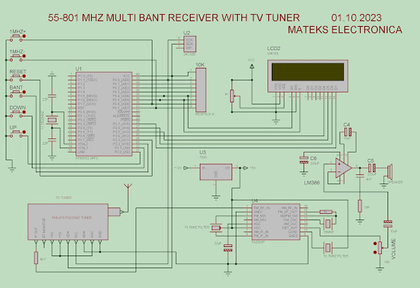
This project is based on the principle of listening to Radio Frequency broadcasts between 55Mhz-801Mhz frequencies with a 50Khz step interval by controlling the PHILIPS FQ1236L Analog TV tuner removed from a scrap TV with the Atmel AT89S52 Microcontroller.
The project was created by bringing together the following components:
1. PHILIPS FQ1236L Analog TV Tuner
2. ATMEL AT89S52 Microcontroller
3. HD44780 based 16X2 LCD screen
4. 24C02 EEPROM
5. TA2003 IC based FM IF (Intermediate frequency) stage
6. LM386 IC based Audio frequency output (Amplifier) stage.
BASIC WORKING PRINCIPLE
The Tuner is programmed to the desired frequency via I2C communication protocol signals generated by the Microcontroller. Since the Tuner used in this project works according to the NTSC broadcasting system, the IF output frequency is 45.75 Mhz. This frequency is reduced to the standard FM IF value of 10.7 Mhz via the TA2003 FM IF circuit, the necessary amplification is made, and finally, the IF frequency is demodulated and the audio signal required for the audio frequency output stage is obtained from its output. This audio signal is amplified in the LM386 audio frequency amplifier circuit and listened to from the speaker.
WORKING PRINCIPLE OF THE PROGRAM
- The 89S52 Microcontroller controls the entire process. When the circuit is first run, it reads the frequency value recorded in the 24C02 EEPROM and determines the frequency to be listened to by sending this frequency value to the Tuner via I2C communication protocol signals. It also writes this frequency to the LCD screen.
- With the UP or DOWN buttons, the frequency can be changed in Up or Down steps of 50Khz, respectively. As long as the buttons are pressed, the frequency automatically increases or decreases.
- With the 1MHZ+ or 1MHZ- buttons, the frequency can be changed in Up or Down steps of 1MHZ, respectively. As long as the buttons are pressed, the frequency automatically increases or decreases.
- When the band end frequency is reached with the UP or 1MHZ+ button, it automatically jumps to the band beginning frequency. Similarly, when the band beginning is reached with the DOWN or 1MHZ- button, it automatically jumps to the band end frequency.
- By pressing the RESET button, the frequency is brought to the initial value of 55 Mhz.
- When the RESET button is pressed for 1 second, the frequency currently being listened to is saved to the EEPROM. After that, the device starts listening from this saved frequency at every startup.
- With the BAND button, the following three bands are selected:
VHF-L: Listens to frequencies between 55MHZ-160MHZ.
VHF-H: Listens to frequencies between 160MHZ-442MHZ.
UHF: Listens to frequencies between 442MHZ-801MHZ.
INFORMATION ABOUT THE CIRCUIT
* The circuit and program design is made according to the Philips FQ1236L tuner. The PLL IC used in this tuner is TDA6509. This software can be used in tuners with the same characteristics and programming format (compatible with I2C programming technique) as this PLL IC. For detailed information, the datasheet of the tuner to be used should be consulted. Tuner pin connections are not standard. Therefore, it is the user's responsibility to find the necessary pins in accordance with the tuner datasheet, if any, or the PLL IC datasheet used in the tuner. Faulty electrical connection may damage the circuit completely or partially.
* The circuit is designed for NTSC broadcasting system. Therefore, the tuner IF output frequency is 45.75 Mhz. In order to make the tuner output suitable for 10.7 Mhz FM IF value, 35 Mhz is used as the crystal value in TA2003 IF circuit (45.75-35=10.75 Mhz).
* When IF value is taken as 38.9 Mhz for PAL system (Türkiye, Europe), 28.2 Mhz crystal should be used. (38.9-10.7=28.2 Mhz). If exact crystal value cannot be found, +500khz, -500kz different crystal can be used.
* Progisp ver1.72 program can be used with Usbasp programmer to load .hex file to AT89S52 microcontroller.
* A standard HD44780 processor based 16x2 LCD is used as the LCD screen.
Picture 4. FM IF PCB drawn in ta2003_if.lay6 Sprint Layout 6.0
FILE DESCRIPTIONS
1. teprom53.hex is the .hex file to be downloaded to AT89S52 Microcontroller for NTSC broadcast system.
2. teprom53_pal.hex is the .hex file to be downloaded to AT89S52 Microcontroller for PAL broadcast system (Türkiye or Europe).
3. teprom53.pdsprj file is the circuit diagram file prepared in Proteus8.
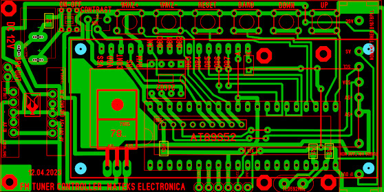
4. teprom521.lay6 is the main pcb file prepared in Sprint layout 6.0 drawing program.
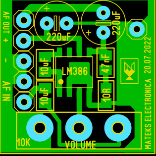
5. lm_386_smd_amplificator.lay6 is the audio frequency amplifier pcb file prepared in Sprint layout 6.0 drawing program.
6. ta2003_if.lay6 is a 10.7 Mhz FM IF circuit pcb file prepared in Sprint layout 6.0 drawing program.
LINKS FOR PROJECT FILES:
https://we.tl/t-Ygi4DqLSrL
https://www.mediafire.com/file/b40bm2qde6qfr2l/MULTIBANT_RECEIVER.rar/file
You can share any questions, suggestions or opinions you have about the project with me.
GOOD LUCK!!
THE FOURTEENTH DAY OF OCTOBER, 2023 A.D.
14/10/2023
MATEKS ELECTRONICA/MEXICO
mateksmakina@hotmail.com


Tesserkurler,
ReplyDeleteIt was very useful for me this video, thank you very much.
ReplyDeleteThanks for your comment.
DeleteMerhaba
ReplyDeleteÇok akıllı ve kullanışlı. Kendim uygulamaya çalışacağım.
ReplyDeleteTeşekkürler.
DeleteÇok iyi anlatılmış. Kendi alıcımı oluşturmak için sabırsızlanıyorum.
ReplyDeleteTeşekkürler.
DeleteWell done!
ReplyDelete